Create a Custom Hydraulic Clutch System for T-5 Upgrades: 65-66 Mustangs
I’d seen several other websites where home designed hydraulic clutch systems were used. I tried to use their information as much as possible. All of the current systems are designed primarily around the CNC brand of parts. These sites include:
Article
on Tremec and Clutch Install
Stangnet
article on install of a JMC Clutch kit
Matt
Swabb’s Article on installing in a 68
Glen’s
Hydraulic Clutch Install
These sites became the basis of how I researched and performed my clutch install. All these sites do a great job of explaining the basics of the system (M/C, Slave, hose), but still leave some of the design/fabrication issues to the builder (Except for the JMC kit, which comes complete). Hopefully I can shed some light on that part
Locating the Master Cylinder: I chose to do all the part locating off the car in a mock up. I removed the pedal support, pedals, and the brake master cylinder. Then, on the bench, I bolted the pedal assembly and M/C together with a spacer plate that duplicated the firewall. It had the existing clutch rod hole, Brake M/C hole, and pedal support hole pattern. This was done to 1) duplicate the car and get the best angle on the firewall for the clutch M/C and 2) find the proper alignment to drill the new attach hole in the clutch pedal.
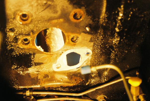
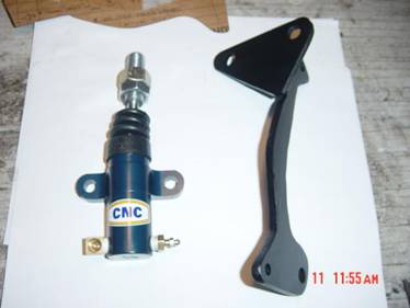
The off the shelf CNC 711 master cylinder comes with the mounting flange welded vertically. (The JMC kit uses a specially modified CNC master cylinder where the flange is relocated horizontally and the unit is canted.) The off the shelf unit has to be tilted approx 45 degrees in order to be centered in the existing clutch hole and still clear the mounting flange of the brake master cylinder. The photo (top right) shows a template made from the flange of the M/C. It is taped in position and used to drill the clutch M/C attach bolts.
Mounting the Master Cylinder: While on the bench during mockup, the shape of the internal anchor plate could be determined. Starting out in the shape of the clutch M/C mounting flange, it get’s oversized to provide a larger footprint. The plate needs to 1) cover an area as large as possible, 2) not hang over the edge of the firewall bumpout (serves no purpose), 3) keep from hitting the forward pedal support bracket, and 4) keep from hitting the steering column. I made 2 identical plates of 1/8” plate steel, then bolted the M/C to them on the inside of the firewall with 7/16” grade 8 bolts and locking washers.
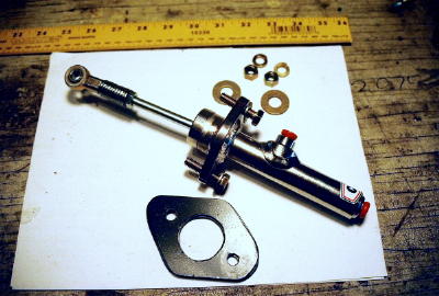
Note: The existing pushrod was not long enough to mount the heim joint. An extension was fabricated by taking a 1.5" section of a 5/8" bolt, center drilling and tapping with 5/16-24 threads, and attaching one end to the pushrod. Then the heim was connected by using a 5/16-24 threaded rod 1" in length.

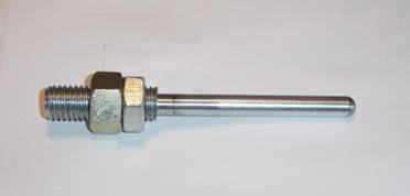
A 5/8” x 2 ½” bolt was acquired, and then center drilled & tapped to fit the 3/8-24 threaded adjusting rod. Since the adjusting rod comes treaded only approx 1”, the last 1½” of the bolt is drilled slightly larger for the rod to fit in…then start threading. The last step is to cut bolt head off at the thread root and screw onto the threaded rod.
The large hex nut becomes the shoulder which actually engages the clutch throwout arm. The second hex nut is a locknut. The threaded portion of the 5/8” bolt fits through the arm and acts as a guide.
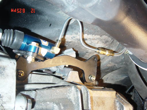
The slave cylinder attach bracket is the biggest freeform portion of this project. There are two “ears” on the T-5 which are in the correct position to hold a horizontal bracket. The holes are 3/8” in these ears are 7” apart OC. The bracket should be made of ¼” plate and has to be shaped in such a manner as to clear the surrounding structure. The Vertical face is welded perpendicularly to the long arm, and provides the surface to mount the slave cylinder. These slave mount holes are 2 3/8” apart OC. Note in the photo below, how the bracket makes room for the slave cylinder, yet works around the boss structure of the transmission.
You will need to fit check in order to find where to weld the vertical face to the horizontal, but the upper hole is roughly 5/8” above the centerline of the horizontal plane, and ½” forward of the forward most horizontal attach bolt hole. I know that is confusing, but if you make templates and lay them out, these dimensions should help. If you're not inclined to build one, then look here as a source.
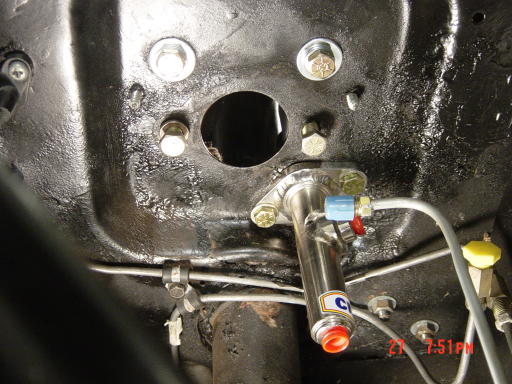
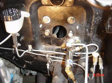
Hydraulic Clutch Line: The Longacre 36” braided stainless steel line is more than adequate for running the fluid to the slave cylinder. I ran it down under the steering column, tied it to the speedometer cable, then ran it back along the fuel & brake lines. From there I made a 180 turn back along the transmission mount and up to the short hard line shown in the photo to the right. It is secured with zip ties in increments and is out of the way of any exhaust pipes.
Parts List/Sources/Prices (March05)
| Parts List: | CNC 711-3/4 Stainless Steel Master Cylinder | CarShop Inc. | $61.95 |
| CNC 305-B Push Style Slave Cylinder | CarShop Inc. | $49.95 | |
| LONGACRE 2805 Hydraulic Clutch Line 36” | CarShop Inc. | $28.95 | |
| CNC 1312 ADJUSTING ROD FOR 305-B | CarShop Inc. | $13.95 | |
| 5/16-24 Ball Joint Rod End | McMaster | $5.50 | |
| Remote Clutch Reservoir | Salvage Yard | $10.00 | |
| Clutch Arm Return Spring | $7.00 | ||
| ¼” x 12 x 12 Plate Steel (Slave Bracket | Scrap Iron | $2.00 | |
| ¼” x 4 x 4 Plate Steel (Firewall Plate) | Scrap Iron | $2.00 | |
| Miscellaneous bolts, washers, screws | $8.00 | ||
| Slave Cylinder Bracket | Homemade - Alternative |
Bleeding Instructions
|
Pumping will only aerate the fluid and prevent complete bleeding. When finished be sure to run master cylinder only 3/4 full of fluid.